How can I model a positive displacement pump using Pipe Flow Expert?
Modelling Positive Displacement Type Pumps
Positive Displacement (PD) pumps generate fluid flow by trapping a fixed volume of fluid that is then forced (displaced) into the discharge pipe. Generally there are three different types of PD pumps, namely rotary type, displacement type, and linear type.
Rotary type PD pumps typically rely on the action of rotating gears, vanes or screws, where as displacement type PD pumps rely on a moving piston or a diaphragm, and linear type PD pumps rely on a chain or a rope.
A positive displacement pump normally operates within a narrow range of flow values, for which there is a relatively wide range of pump head values.
Positive displacement pumps do not always pump to their full capacity due to “slippage”. There will always be a small clearance between the pump's moving parts and the pump housing, and for fluids with low viscosity it is possible for some of the fluid to slip through this clearance gap, from the outlet side of the pump back to the inlet side. When this slippage occurs it means that the pump does not pump at its full capacity.
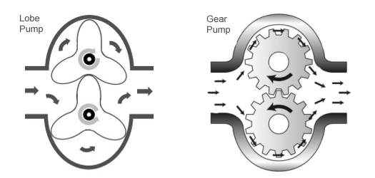
The following diagram illustrates the internal components of a typical rotary type positive displacement lobe pump and gear pump:
There are a number of different methods that can be used to model a positive displacement pump using the Pipe Flow Expert software and these are described below.
Method One: Fixed Flow Pump
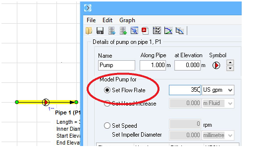
You can model the pump in Pipe Flow Expert as a “fixed flow” pump, by selecting the “Set Flow Rate” option within the pump data screen. When you solve the system with a fixed flow pump, Pipe Flow Expert will calculate the pump head required to achieve the specified flow rate while taking account of all of the other flows and pressure losses through the system.
The following image shows the Pipe Flow Expert pump data screen with a fixed flow mode of operation specified:
Once the system is solved the user must check that the calculated pump head (required to produce the specified flow rate) can be produced by the chosen positive displacement pump when run at a particular speed.
Method Two: Fixed Flow Pump with Slippage Modelling
As per Method One, the pump is modelled as a “fixed flow” pump, by selecting the “Set Flow Rate” option within the pump data screen. However in this approach, the pump slippage (as described above) is also included in the modelling.
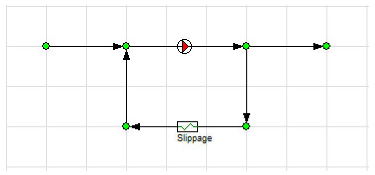
Slippage can be modelled in the logical model by adding in a pipe that returns flow representing the slippage from the outlet side to the inlet side of the pump. A Component with suitable flow versus pressure loss data (that represents the slippage) is included on the pipe. This is shown in the diagram below:
As with Method One, when you solve the system Pipe Flow Expert will calculate the head required to achieve the specified flow rate upon consideration of all of the other flows and pressure losses through the system. Again the user must check that the calculated pump head (required to produce the specified flow rate) can be produced by the chosen positive displacement pump when run at a particular speed.
Method Three: Pump Performance Curve
An alternative approach to using a fixed flow pump is to specify a pump performance curve for the positive displacement pump within the Pipe Flow Expert software. Due to the narrow range of flow rates that a PD pump will operate over for a given pump speed, and also given that Pipe Flow Expert needs to have a pump head value specified for the zero flow rate condition (normally used to specify the shut off head on a Centrifugal pump), only a narrow region of the generated pump performance curve will be valid for the Positive Displacement pump.
Note: It is up to the user to calculate a suitable pump head value to enter for the zero flow rate condition by extrapolating the positive displacement pump flow versus head data (which normally follows a fairly straight line). This will then 'extend' the performance curve of the PD pump for modeling purposes (basically to allow the use of the pump curve model within Pipe Flow Expert) however the user should always remember that the calculation results will only be valid if the actual calculated operating flow rate when the system is solved, falls within the part of the pump performance curve which defines the range of flow rates that are applicable to the PD pump.
Positive displacement pump performance data is often plotted as a series of lines on a flow rate vs. pump speed graph, where each line represents a specific pressure that is added (pump head). Such data can be transposed onto a pump head vs. flow rate graph, for entry into Pipe Flow Expert.
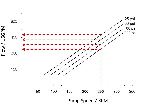
Consider the diagram above: For a given pump speed, as defined on the x-axis, each flow rate / pump head data point can be derived by identifying the point where each pressure line crosses the x-axis for the selected pump speed. You will need to extrapolate from the data thus obtained, in order to estimate the pressure (pump head) data point that corresponds to a zero flow rate, as this data point is needed by Pipe Flow Expert.
These data points can then be entered into the Pipe Flow Expert pump data screen to define the pump performance curve.
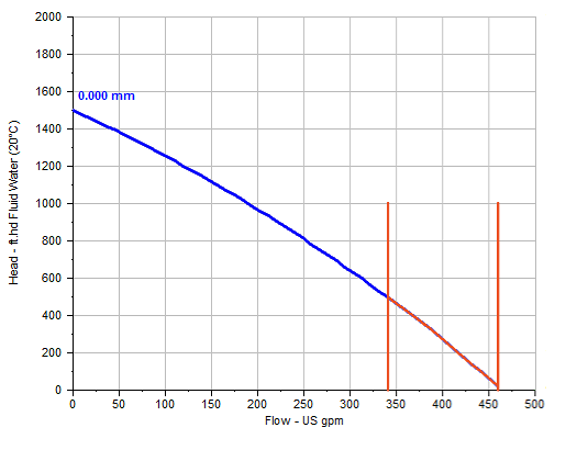
The diagram below shows a pump performance curve for a PD pump, with the operating range highlighted in red:
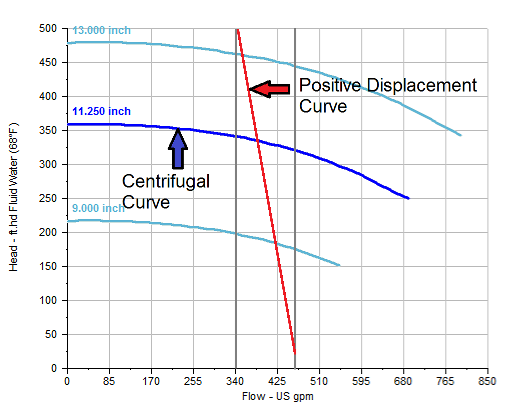
 For comparison, the following image shows the same positive displacement pump performance curve superimposed on top of a performance curve for a centrifugal pump. This image highlights the comparatively narrow range of flow rates that a positive displacement pump operates over in relation to the much wider flow range of a centrifugal pump. It also shows the comparatively 'steep' descent of the performance curve for the PD pump which is not shown on the previous image above, due to the spacing and scaling of the graph around just the PD pump data.
IMPORTANT NOTE:
If the resultant flow rate that is calculated when solving the system lies outside of the narrow region of flow of the PD pump, then the calculation results must be treated as invalid. The software will not provide any warning in regards to this issue and it is up to the user to manually check that the calculated operating point on the pump curve falls within the narrow flow region of the PD pump.
For a given PD pump, a pump performance curve is specific to a particular fluid, so for different fluids you will need different performance curve data for the PD pump. The density and viscosity of different fluids will also affect the amount of slippage that occurs within a PD pump.