

Contraction K
Contraction fittings are used to model a sudden or gradual decrease in pipe diameter. The loss coefficient (K) for a contraction depends on the flow characteristics, the change in pipe size, and the geometry of the contraction. For these fittings the K value is calculated automatically based on:
Reynolds Number, accounts for the effect of flow regime on the contraction loss, particularly the difference between low-Reynolds-number and turbulent-flow behaviour.
The upstream and downstream diameters, define the change in flow area and therefore the magnitude of the contraction.
(theta), the contraction angle, defines how abruptly the pipe diameter decreases.
Sudden Contractions
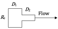

Where:
k = Sudden contraction loss coefficient K value (for use with velocity on the upstream pipe).
D1 = Internal diameter of the upstream (larger) pipe.
D2 = Internal diameter of the downstream (smaller) pipe.
Re = The Reynolds number.
f1 = Friction factor for the upstream pipe.
θ = Contraction angle (180o)
Gradual Contractions
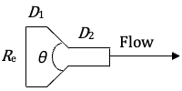
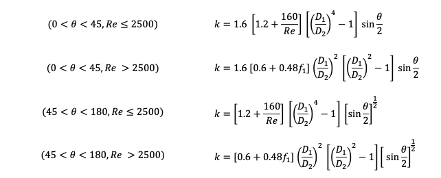
Where:
k = Gradual contraction loss coefficient K value (for use with velocity on the upstream pipe).
D1 = Internal diameter of the upstream (larger) pipe.
D2 = Internal diameter of the downstream (smaller) pipe.
Re = The Reynolds number.
f1 = Friction factor for the upstream pipe.
θ = Total included contraction angle of the conical section (in degrees)
The Expansion K and Contraction K equations are as defined in Hooper, W.B., "Calculate Head Loss Caused by Change in Pipe Size," Chemical Engineering, 95(16), pp. 89-92, November 7, 1988.
Note: The original equations use the Fanning friction factor. The equations above have been converted to use the Darcy friction factor (f₁), where f_Darcy = 4 × f_Fanning.