Pipe Flow Software for Flow Rate, Pressure Drop & Pump Calculations

Pipe Flow Expert Software is used by piping system & hydraulic engineers in over 100 countries worldwide.
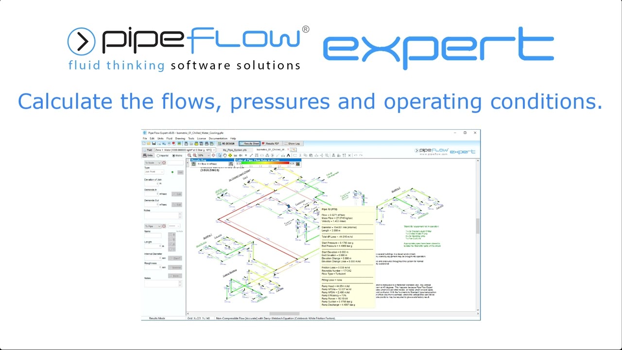
The software calculates flow rates, pipe pressure drops, and pump performance. It can model pipe systems with multiple supply points, discharge tanks, components, valves, & multiple pumps in series or in parallel.

 Quick Start Videos - Pipe Flow Expert Software
Quick Tips Videos - Pipe Flow Expert Software
Quick Start Videos - Pipe Flow Expert Software
Quick Tips Videos - Pipe Flow Expert Software
Technical Videos - Pipe Flow Expert Software
 Calculate Pump Head Required For a Given Flow Rate
See why engineers in over 100 countries worldwide use Pipe Flow Expert Software
Frequently Asked Common Questions - Pipe Flow Expert Software
Frequently Asked Technical Questions - Pipe Flow Expert Software
Pipe Flow Expert Software - for designing piping and pumping systems

The Pipe Flow Expert Software can be used to model pipe systems with just a few pipes through to more complex systems with many hundreds of pipes. Find out how the Pipe Flow Expert Piping Design Software can help you (just like it helps other professional engineers in over 100 countries worldwide).
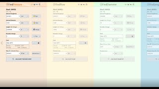
Pipe Flow Wizard Software - for single pipe calculations

The Pipe Flow Wizard Software Calculator can be used to find flow rate, pressure drop, pipe size, or pipe length, based on a single pipe calculation. Find out how the Pipe Flow Wizard Single Pipe Calculator can help you perform calculations on a single length of pipe, saving you time & effort, and improving the reliability of your calculated results.
Pipe Flow Advisor Software - for open channel calculations

The Pipe Flow Advisor Software can be used to calculate flow rates in open channels, work out tank empty times, and find volume of different shapes. Find out how the Pipe Flow Advisor Software for Channel & Tanks can help you with your channel, tank, and volume calculations.
Pipe Flow Software Customer Testimonials
Great software, superlative service.
It is one of the best programs in its genre that I have ever used.
Easy-To-Use, Unbeatable Value, Unrivalled Support!
Buy online now and get licensed in < 2 minutes

Hydraulic Calculations
Useful links related to the calculation of fluid flow type, flow rate, friction loss and total pressure drop in a pipe.
Fluid Density Calculations Fluid Viscosity Calculations Laminar and Turbulent Flow Pipe Roughness Reynold's Numbers Friction Factor Calculations Friction Loss Calculations Pressure Drop Calculations Pipe Flow Calculations
|
Pipe Flow Software
Suite 3, Courthill House, Water Lane, Wilmslow, Cheshire, SK9 5AJ, England. Phone: +44 161 408 3569. https://www.pipeflow.com. |